| Author |
 Topic Search Topic Search  Topic Options Topic Options
|
seti007 
Guest


Joined: March 19 2003
Location: Holladay
Status: Offline
Points: 1157
|
 Post Options Post Options
") Thanks(0) Thanks(0)
 Quote Quote  Reply Reply
 Topic: Super cheap Dimmable LED Driver (cost under $3) Topic: Super cheap Dimmable LED Driver (cost under $3)
Posted: March 11 2011 at 10:05pm |
LEDs are all the rage these days and a lot of peopel are doing DIY projects withe them. I thought I'd post a simple and very easy to build DIY driver that Im using on my tank. I originally went with a design based on cat4101 chip that could drive 6-7 3watt LEDs depengin in the forward voltage. But I found some issuees with the CAT4101 chip that forced me to look elsewhere.
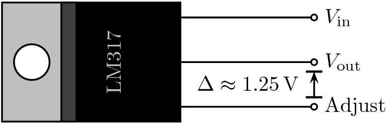
The design is based on the LM317 chip and can be made simply using one single resistor. The LM317 I used is a TO-220 package and has 3 pins. It can be operated in a constant current mode to drive LEDs like the one's most people use on their tanks i.e. Cree, Luxeon or Steve's LEDs. Here is a pic of the chip I found online.
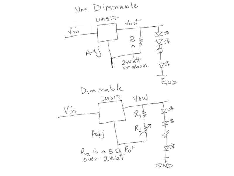
Here is a pic of the The design works flawlessly and drives 6 + LEDs in series per chip based on the forward viltage of the LED chip and the supply voltage.
The way to calculate the size of the resistor to use is super simple Ohm's law
R=1.25/I where I would be the desired current through the LEDs. Although the part is rated at 1.5A, I would not recommed anything over 1A to keep the heat factor down ( I suppose you could go higher but use a higher wattage resistor and a larger heat sink). I would also recommend a heat sink on the chip to keep things cool. It is also receommended that you use a .01uF cap at the input if the power supply is noisy but I did not bother since I have a good quality Mean well switching supply that puts out a pretty good DC signal. Keep in mind that the Heat sink I used is a huge over kill. I just had a bunch laying around and used them. An aluminum U channel would work just as good. I am driving 7x 3watt Steve's LEDs based on an input voltage of ~24v with each one of the LM317 chips. The chips cost ~$.50 online and $1.50 locally at RaElco. The resistors are about $.70 each so the total cost to drive each string of 7LEDs for me was $2.20  not including heat sinks not including heat sinks since I already had those. The dimmable ones would be a few dollars more but still way less that anyting else out there. I've been using these to drive about 100 LEDs over my 150 gal cube and the colors are just amazing.
If anyone is thinking about building a DIY LED setup, Ill be happy to help you out. You are welcome to come check out my setup as well.
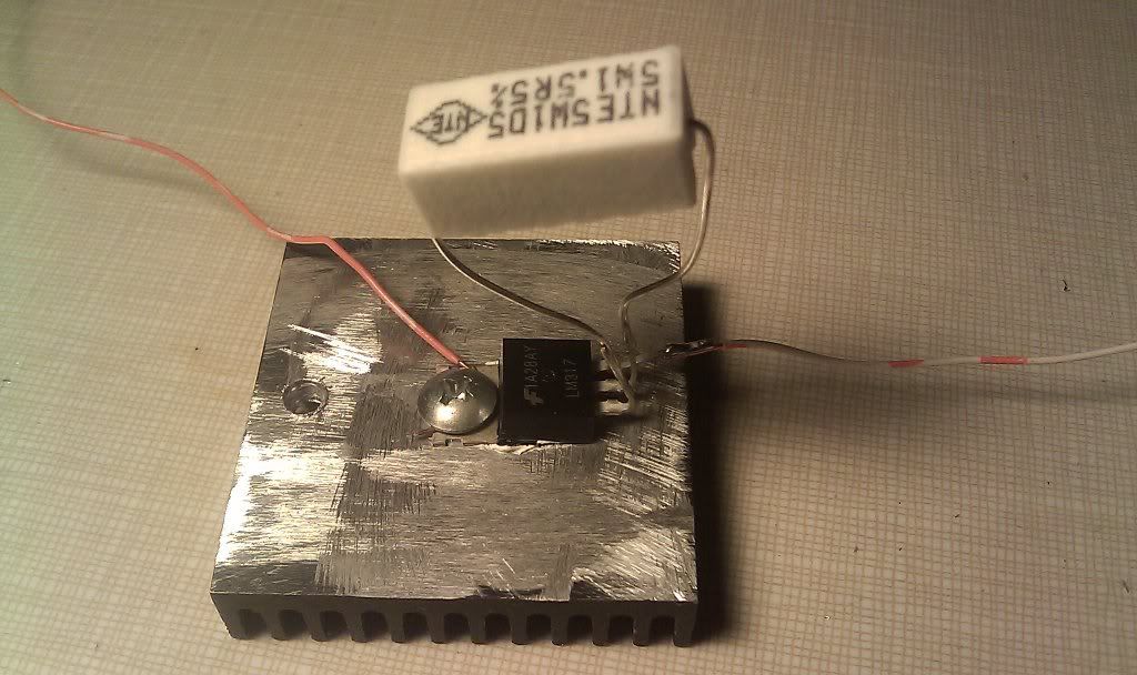
Here is a pic of the assembled driver. Im driving my LEDs at 850mA.
Edited by seti007 - March 11 2011 at 10:21pm
|
Any sufficiently advanced technology is indistinguishable from magic--Arthur C. Clarke

|
 |
Crazy Tarzan
Guest
Joined: September 12 2003
Location: Riverton, WY
Status: Offline
Points: 1681
|
Post Options
Thanks(0)
Quote Reply
Posted: March 11 2011 at 11:29pm |
I'm interested in this. How would you wire a dimmable set up? What type of power supply would you use? I am currently running 2 meanwells with 12 cree XR-E on each. I'm looking to up it to 48 cree's and wouldn't mind a less bulky, less expensive dimmable set up.
|
|
Was that in there yesterday? Casper--WY windier than ?
Down to a 20, soon to double or nothing
|
|
Mark Peterson
Paid Member


Joined: June 19 2002
Location: Murray
Status: Offline
Points: 21436
|
Post Options
Thanks(0)
Quote Reply
Posted: March 12 2011 at 8:45am |
|
Asad, that's awesome. Your new LED lights are awesome. I'm so happy that you are going to be on the RT. Your tank is AWESOME.
I've been meaning to ask you to help me put together an LED light bar for my Dentist's hang on the wall tank. Those aluminum T-bar heat sink mounting strips are just perfect for the 40x4.5x21 tank. I'll call you.
|
Reefkeeping Tips, & quick, easy setup tricks:www.utahreefs.com/forum/forum_posts.asp?TID=9244 Pay it forward - become a paid WMAS member 
|
|
Davidwillis
Guest
Joined: July 30 2005
Location: Weston Id
Status: Offline
Points: 605
|
Post Options
Thanks(0)
Quote Reply
Posted: March 12 2011 at 9:40am |
Wow!!! this is exactly what I am looking for. I have my LED's on order, and have my 24v power supply, but did not know how to do this, and I don't want to buy them for $15 each.
I want to run two series of 8-12 LED's (I may have to break it up into 3 with only 24 volts), and I want them dimmable.
Where did you find these online?
Thanks again, this is perfect.
|
|
seti007
Guest
Joined: March 19 2003
Location: Holladay
Status: Offline
Points: 1157
|
Post Options
Thanks(0)
Quote Reply
Posted: March 12 2011 at 10:00am |
 Crazy Tarzan wrote: Crazy Tarzan wrote:
I'm interested in this. How would you wire a dimmable set up? What type of power supply would you use? I am currently running 2 meanwells with 12 cree XR-E on each. I'm looking to up it to 48 cree's and wouldn't mind a less bulky, less expensive dimmable set up.
|
I am using one meanwell power supply model number SP-320-24. I got it off ebay for about $42 shipped. It puts out 24V at 13A max. My recommendation would be to drive this or any power supply to a max of 80% of its rated power that owuld mean that you should drive it at a max of 10.4 A which would equate to about 250 Watts. The LEDs im using have a Vf of 3.2-3.3 V so I can drive 24/3.2=~7.5 ( or 7 in my case) LEDs in series. My desired current was ~850mA that means I could drive 10.4/.850=~12.2 rows(or 12 rows) of 7 LEDs each driven by an LM317 off just this one power supply. That would make 12x7= 84 LEDs driven off the meanwell SP-320-24. Hope that makes sense. If not, LMK and I can explain in more detail or over the phone.
I also have a smaller 24V power supply to drive the rest of the LEDs in a similar fashion. The neat thing is that I can add more rows if needed at any time to the other power supply. Another thing to consider is that imho its better to have a few smaller power supplys and turn them on one at a time rather than have a large power suplpy and have t turn a bunch of LEDs on at the same timme. Remmber that the inrush current of the SP-320-24 is 20A at 120V  so a couple of these turning on at the same time could trip the circuit breaker.
|
Any sufficiently advanced technology is indistinguishable from magic--Arthur C. Clarke
|
|
seti007
Guest
Joined: March 19 2003
Location: Holladay
Status: Offline
Points: 1157
|
Post Options
Thanks(0)
Quote Reply
Posted: March 12 2011 at 10:04am |
Davidwillis wrote:
Wow!!! this is exactly what I am looking for. I have my LED's on order, and have my 24v power supply, but did not know how to do this, and I don't want to buy them for $15 each.
I want to run two series of 8-12 LED's (I may have to break it up into 3 with only 24 volts), and I want them dimmable.
Where did you find these online?
Thanks again, this is perfect.
|
Dave that would depend on the voltage drop across the LEDs you are using. In My case, if I had to drive the same number of LEDs you are wanting to, I would have to have 7 LEDS x3 rows. The meanwell power supply I mentioned above has a trim pot that can be adjusted to vary the voltage slightly above or below 24v which comes in real handy while fine tuning the system to make it run as efficeiently and cool (temp wise) as possible.
Mark, thanks for the kind words. Im looking forward to be in the Reef tour.
Edited by seti007 - March 12 2011 at 10:05am
|
Any sufficiently advanced technology is indistinguishable from magic--Arthur C. Clarke
|
|
saltlaketank
Guest

Joined: March 08 2011
Location: West Valley
Status: Offline
Points: 289
|
Post Options
Thanks(0)
Quote Reply
Posted: March 12 2011 at 1:48pm |
well that looks like a sinch. 
|
|
JayDee 8016042780
90 Gallon
30 Gallon sump
G3 Skimmer
|
|
Davidwillis
Guest
Joined: July 30 2005
Location: Weston Id
Status: Offline
Points: 605
|
Post Options
Thanks(0)
Quote Reply
Posted: March 12 2011 at 8:59pm |
seti007 wrote:
Davidwillis wrote:
Wow!!! this is exactly what I am looking for. I have my LED's on order, and have my 24v power supply, but did not know how to do this, and I don't want to buy them for $15 each.
I want to run two series of 8-12 LED's (I may have to break it up into 3 with only 24 volts), and I want them dimmable.
Where did you find these online?
Thanks again, this is perfect.
|
Dave that would depend on the voltage drop across the LEDs you are using. In My case, if I had to drive the same number of LEDs you are wanting to, I would have to have 7 LEDS x3 rows. The meanwell power supply I mentioned above has a trim pot that can be adjusted to vary the voltage slightly above or below 24v which comes in real handy while fine tuning the system to make it run as efficeiently and cool (temp wise) as possible.
Mark, thanks for the kind words. Im looking forward to be in the Reef tour. |
How much can you adjust your meanwell power supply? It would be really nice to have a power supply that would be able to adjust from 20-35 V.
Also, where can you find a 5 ohm Pot? They don't seem that common.
|
|
seti007
Guest
Joined: March 19 2003
Location: Holladay
Status: Offline
Points: 1157
|
Post Options
Thanks(0)
Quote Reply
Posted: March 13 2011 at 8:09pm |
Davidwillis wrote:
How much can you adjust your meanwell power supply? It would be really nice to have a power supply that would be able to adjust from 20-35 V.
Also, where can you find a 5 ohm Pot? They don't seem that common. |
The meanwell can be adjusted from about 22-26v IIRC . I have found that to be perfect if im driving 6-8 3W LEDs in series. The 5Ohm Pots can be found on ebay. You are right they are not very common. Try looking for a 5Ohm Rheostat as well but they are higher wattage and usually more $$. Check out this auction with 4 pieces( POTs) for $11 delivered
http://cgi.ebay.com/ws/eBayISAPI.dll?ViewItem&item=300535769006
Edited by seti007 - March 13 2011 at 8:11pm
|
Any sufficiently advanced technology is indistinguishable from magic--Arthur C. Clarke
|
|
Davidwillis
Guest
Joined: July 30 2005
Location: Weston Id
Status: Offline
Points: 605
|
Post Options
Thanks(0)
Quote Reply
Posted: March 13 2011 at 8:30pm |
|
That is interesting. Could you use an adjustable voltage regulator before the LM317 to do the dimming? Or would that cause problems? It looks like the efficiency of these will really go down if you dimm them (you will still use as much power as when on full, but you will be just wasting some to dimm the light).
|
|
seti007
Guest
Joined: March 19 2003
Location: Holladay
Status: Offline
Points: 1157
|
Post Options
Thanks(0)
Quote Reply
Posted: March 13 2011 at 8:35pm |
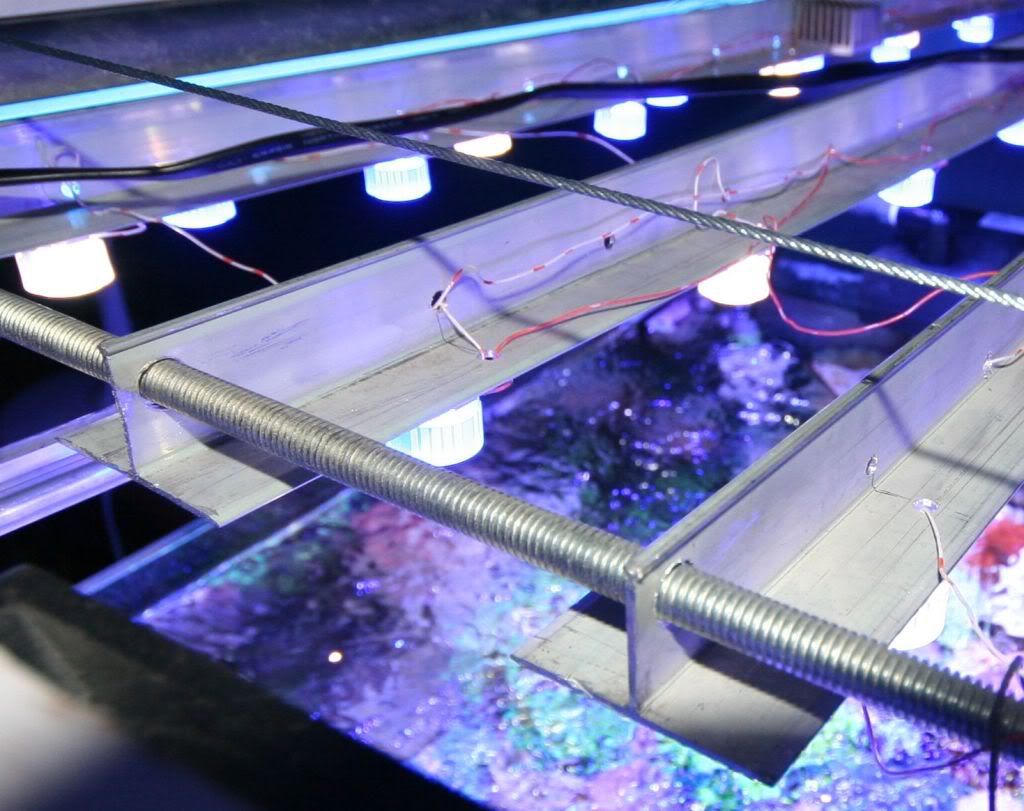
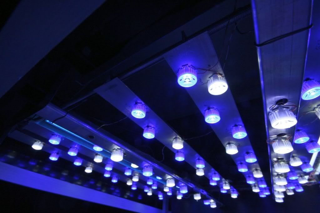
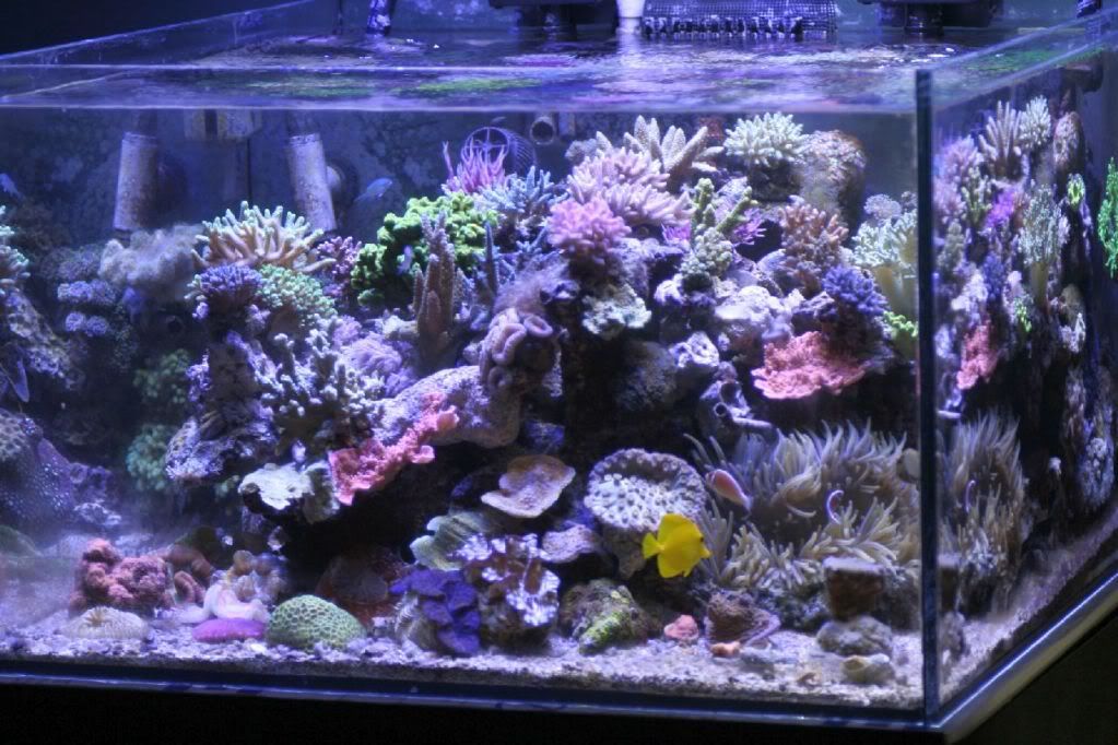
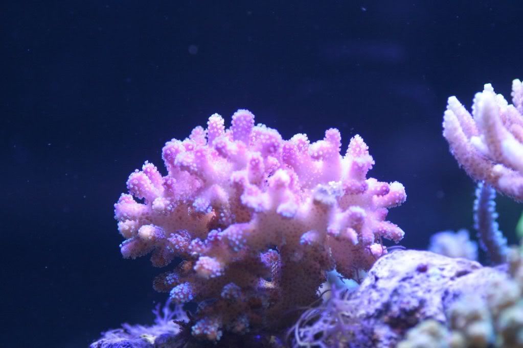
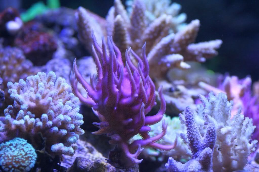
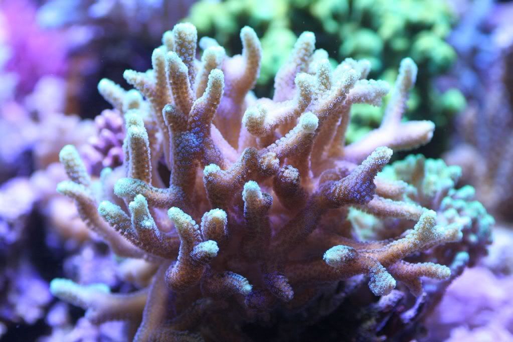
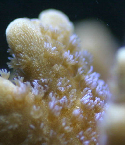
I have been running the LEDS on my tanks for about a month or so and initially i was worried about the corals losing color. However, so far Im pretty happy with the results. Most corals have colored but a bit more than before on T5 lights. Here are some pics of the actual LED fixture. It looks dim but trust me, its super bright.
First the Aluminum T channel heat sinks. The LEDs are attached using Heat conducting double sided tape.
LEDs with 30 degree optics
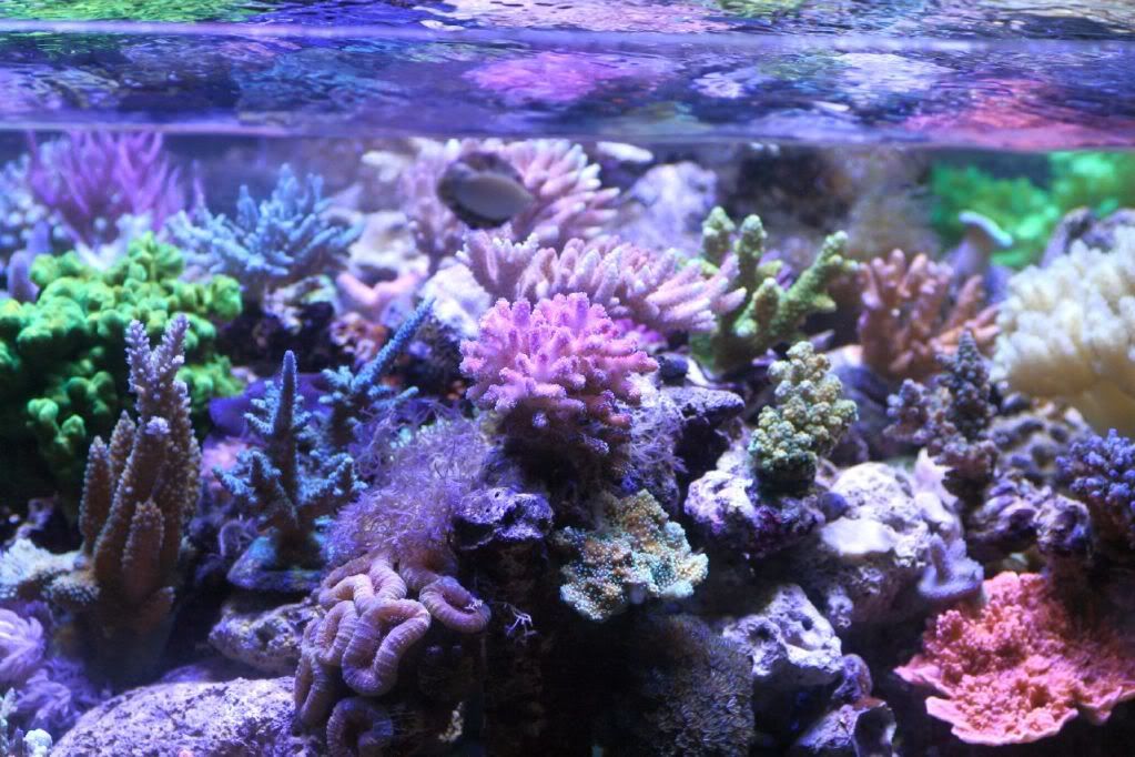
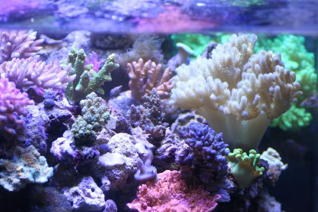
Now for some tank and coral shots under the LEDs
Edited by seti007 - March 13 2011 at 8:37pm
|
Any sufficiently advanced technology is indistinguishable from magic--Arthur C. Clarke
|
|
seti007
Guest
Joined: March 19 2003
Location: Holladay
Status: Offline
Points: 1157
|
Post Options
Thanks(0)
Quote Reply
Posted: March 13 2011 at 8:42pm |
Davidwillis wrote:
That is interesting. Could you use an adjustable voltage regulator before the LM317 to do the dimming? Or would that cause problems? It looks like the efficiency of these will really go down if you dimm them (you will still use as much power as when on full, but you will be just wasting some to dimm the light). |
No, you dont want to dim by varying the voltage through the Meanwell. You want to use the adj Resistor. The efficiency does not really drop as you drop the current because the powersupply varies the current as needed by the lm317 circuit. So power being voltagexCurrent, the output power varies depending on the current the LEDs are being driven at. Hope that makes sense.
Edited by seti007 - March 13 2011 at 8:43pm
|
Any sufficiently advanced technology is indistinguishable from magic--Arthur C. Clarke
|
|
Davidwillis
Guest
Joined: July 30 2005
Location: Weston Id
Status: Offline
Points: 605
|
Post Options
Thanks(0)
Quote Reply
Posted: March 14 2011 at 2:04am |
Maybe I don't understand correctly... I am looking here: http://users.telenet.be/davshomepage/current-source.htm
- P=power loss
- U=supply voltage
- Uf=voltage drop device
- I=current
P = ( U - Uf ) * I
My understanding from that is that if you have (just as an example) 40v supply, but your LED's only need 20 to maintain your current (of say 1000ma to keep the math easy). Your power loss is (40-20)*1 = 20W. But if you supply with 24v and need 20, then you end up with (24-20)*1=4W. Or am I not doing that correctly?
Also, I was wondering if you have tried any chips like the LM3401 or ZXLD1360? From what I understand they would be more efficient...???
Edited by Davidwillis - March 14 2011 at 2:04am
|
|
seti007
Guest
Joined: March 19 2003
Location: Holladay
Status: Offline
Points: 1157
|
Post Options
Thanks(0)
Quote Reply
Posted: March 14 2011 at 11:49am |
Davidwillis wrote:
Maybe I don't understand correctly... I am looking here: http://users.telenet.be/davshomepage/current-source.htm
- P=power loss
- U=supply voltage
- Uf=voltage drop device
- I=current
P = ( U - Uf ) * I
My understanding from that is that if you have (just as an example) 40v supply, but your LED's only need 20 to maintain your current (of say 1000ma to keep the math easy). Your power loss is (40-20)*1 = 20W. But if you supply with 24v and need 20, then you end up with (24-20)*1=4W. Or am I not doing that correctly?
Also, I was wondering if you have tried any chips like the LM3401 or ZXLD1360? From what I understand they would be more efficient...???
|
What you state would be true for a linear power supply that would wate the "unused" portion of the power it is supplying thta is why you want to use a switching power supply that can regulate by varying the current at a given voltage. Think of your laptop power supply (also a switchign power supply) when the battery is fully charged and the computer is not doing anything cpu intensive, the power supply, even though it maybe rated at 19v @ 3A does not "burn off" the excess power but rather varys the only supplies whats needed. Try it out by putting a power meter like the kill-a-watt meter in front of a computer. You'll see the power consumed change as you do less or more cpu intensive things on the computer. Same exact principal applies to the LEDs.
That said, there is a way that power can be wasted in the circuit and that would be if the supplied voltage does not match the total voltage drop. In one of my posts above, i mentioned tweaking the trim pot to just the right voltage. I can explain this with the help of an example:
Lets assume that i have a 7 LED array (in series) and the voltage drop is 3.2V across each LED. I'm driving these with an LM317 with a voltage drop of 1.25. So the toal voltage drop is (3.2x7)=1.25=23.65v. I will then turn the trim pot until i get as close to this voltage as I can. Let assume that Im driving this LED array with 850mA. If I were to supply say 24.65v from the power supply instead of 23.65v then the 1v difference would result in a 1v x 800mA =.8Watts of wasted power. that is the equation you mentiuoned above P = ( U - Uf ) * I So what you say above is very true in this scenario. That is why you want to match the voltages as close as possible.
In real life you will have to physically measure the voltage drops with a volt meter and that would be different for LEDS of even the same bin #s. The total voltage drops across each one of the multiple LED array would undoubtedly differ slightly so you will for sure have a bit of wasted power but the overall design will still be a lot more efficient than say Metal Hlides.
As for using other chips, as I mentioned, i have tried the cat4101 ( see the huge reefcentral thread) but i had some bad luck with that design. Even though the CAT4101 is a lot more efficient, i decided to go with the LM317 because of the simplicity, availability and cost. It works well for me. That is not to say that other designs would not work.
Edited by seti007 - March 14 2011 at 12:07pm
|
Any sufficiently advanced technology is indistinguishable from magic--Arthur C. Clarke
|
|
Crazy Tarzan
Guest
Joined: September 12 2003
Location: Riverton, WY
Status: Offline
Points: 1681
|
Post Options
Thanks(0)
Quote Reply
Posted: March 14 2011 at 1:48pm |
|
Asad--using this method, can I use the 24v 1A wall warts I find on ebay to run separate strings of 6-7 led? I'm thinking about using 3-4 colors of LED on my next fixture. Also, can you please put the second diagram into layman's terms? I'm interested in doing dimmable fixtures to adjust the color of the lighting.
|
|
Was that in there yesterday? Casper--WY windier than ?
Down to a 20, soon to double or nothing
|
|
seti007
Guest
Joined: March 19 2003
Location: Holladay
Status: Offline
Points: 1157
|
Post Options
Thanks(0)
Quote Reply
Posted: March 14 2011 at 3:04pm |
Crazy Tarzan wrote:
Asad--using this method, can I use the 24v 1A wall warts I find on ebay to run separate strings of 6-7 led? I'm thinking about using 3-4 colors of LED on my next fixture. Also, can you please put the second diagram into layman's terms? I'm interested in doing dimmable fixtures to adjust the color of the lighting. |
If they are a linear powers supply, i would stay away. Most walwarts are simple ac to dc transformer with a rectifier circuit ane not suitable for this project. Besides, if you want to drive them at 80% you are looking at one of these per string of LEDs and depending on how many LEDs yo have you may need a whole lot of them. Another thing these probably wont have is a trim pot to adjust the output voltage by a small amount. As i mentioned earlier, this adjustment is super helpful to make sure the whoile thing runs as efficiently as possible.
|
Any sufficiently advanced technology is indistinguishable from magic--Arthur C. Clarke
|
|
Davidwillis
Guest
Joined: July 30 2005
Location: Weston Id
Status: Offline
Points: 605
|
Post Options
Thanks(0)
Quote Reply
Posted: March 14 2011 at 7:19pm |
seti007 wrote:
Davidwillis wrote:
Maybe I don't understand correctly... I am looking here: http://users.telenet.be/davshomepage/current-source.htm
- P=power loss
- U=supply voltage
- Uf=voltage drop device
- I=current
P = ( U - Uf ) * I
My understanding from that is that if you have (just as an example) 40v supply, but your LED's only need 20 to maintain your current (of say 1000ma to keep the math easy). Your power loss is (40-20)*1 = 20W. But if you supply with 24v and need 20, then you end up with (24-20)*1=4W. Or am I not doing that correctly?
Also, I was wondering if you have tried any chips like the LM3401 or ZXLD1360? From what I understand they would be more efficient...???
|
What you state would be true for a linear power supply that would wate the "unused" portion of the power it is supplying thta is why you want to use a switching power supply that can regulate by varying the current at a given voltage. Think of your laptop power supply (also a switchign power supply) when the battery is fully charged and the computer is not doing anything cpu intensive, the power supply, even though it maybe rated at 19v @ 3A does not "burn off" the excess power but rather varys the only supplies whats needed. Try it out by putting a power meter like the kill-a-watt meter in front of a computer. You'll see the power consumed change as you do less or more cpu intensive things on the computer. Same exact principal applies to the LEDs.
That said, there is a way that power can be wasted in the circuit and that would be if the supplied voltage does not match the total voltage drop. In one of my posts above, i mentioned tweaking the trim pot to just the right voltage. I can explain this with the help of an example:
Lets assume that i have a 7 LED array (in series) and the voltage drop is 3.2V across each LED. I'm driving these with an LM317 with a voltage drop of 1.25. So the toal voltage drop is (3.2x7)=1.25=23.65v. I will then turn the trim pot until i get as close to this voltage as I can. Let assume that Im driving this LED array with 850mA. If I were to supply say 24.65v from the power supply instead of 23.65v then the 1v difference would result in a 1v x 800mA =.8Watts of wasted power. that is the equation you mentiuoned above P = ( U - Uf ) * I So what you say above is very true in this scenario. That is why you want to match the voltages as close as possible.
In real life you will have to physically measure the voltage drops with a volt meter and that would be different for LEDS of even the same bin #s. The total voltage drops across each one of the multiple LED array would undoubtedly differ slightly so you will for sure have a bit of wasted power but the overall design will still be a lot more efficient than say Metal Hlides.
As for using other chips, as I mentioned, i have tried the cat4101 ( see the huge reefcentral thread) but i had some bad luck with that design. Even though the CAT4101 is a lot more efficient, i decided to go with the LM317 because of the simplicity, availability and cost. It works well for me. That is not to say that other designs would not work.
|
Thank you so much for your explanation, it makes perfect sense. The only problem I see is when dimming, and using more than one array of different sizes off the same power supply. If I dimm an array, I would change the voltage drop, and would also need to change the power in to keep it efficient. And If I had two or more arrays, I would need to keep the voltage at the highest voltage drop, making the lower voltage drop arrays less efficient.
I guess I could put something like this on each array: http://cgi.ebay.com/LM2596-DC-DC-Step-Down-Adjustable-Power-Supply-Module-/270712776755?pt=LH_DefaultDomain_0&hash=item3f07bd2833
But that would add some cost, and would still have to be lowered when dimming to keep it efficient.
|
|
Davidwillis
Guest
Joined: July 30 2005
Location: Weston Id
Status: Offline
Points: 605
|
Post Options
Thanks(0)
Quote Reply
Posted: March 14 2011 at 7:38pm |
by the way, can you give me a link to your thread using the CAT4101?
Thanks
Edited by Davidwillis - March 14 2011 at 7:39pm
|
|
seti007
Guest
Joined: March 19 2003
Location: Holladay
Status: Offline
Points: 1157
|
Post Options
Thanks(0)
Quote Reply
Posted: March 14 2011 at 9:57pm |
Davidwillis wrote:
Thank you so much for your explanation, it makes perfect sense. The only problem I see is when dimming, and using more than one array of different sizes off the same power supply. If I dimm an array, I would change the voltage drop, and would also need to change the power in to keep it efficient. And If I had two or more arrays, I would need to keep the voltage at the highest voltage drop, making the lower voltage drop arrays less efficient.
I guess I could put something like this on each array: http://cgi.ebay.com/LM2596-DC-DC-Step-Down-Adjustable-Power-Supply-Module-/270712776755?pt=LH_DefaultDomain_0&hash=item3f07bd2833
But that would add some cost, and would still have to be lowered when dimming to keep it efficient. |
Thats not entirely true, although there would be differences in the voltage drops of the arrays. but when you dim, you are not changing the voltage but rather the current that is becasue the lm317 chip is acting as a constant current driver.
here is the link to the cat4101 thread. They dont start talking about the cat4101 design until much later in the thread. I built these and they worked well until I had some issues with the cat 4101 chips. The manufacturer seems to think its a quality control issue and I currently have these in RMA. Hence, i went with amuch easier and simpler solution that has worked well fo rme.
Edited by seti007 - March 14 2011 at 9:58pm
|
Any sufficiently advanced technology is indistinguishable from magic--Arthur C. Clarke
|
|
seti007
Guest
Joined: March 19 2003
Location: Holladay
Status: Offline
Points: 1157
|
Post Options
Thanks(0)
Quote Reply
Posted: March 14 2011 at 10:01pm |
BTW, that ebay link is a voltage regulator NOT a constant current driver. You would need the latter if you want to not fry your led array. I guess you could use that voltage regulator but then you would have to have a beefy resistor to regulate the current through the array. So to recap you want to drive the led array with a current regulator (AKA a constatnt current driver) and not a voltage driver. The LM317 can be used both ways depending on the circuit design. Im using it in a constant current mode.
Edited by seti007 - March 14 2011 at 10:10pm
|
Any sufficiently advanced technology is indistinguishable from magic--Arthur C. Clarke
|
|


")